How to model an unconformity
How to model an unconformity is an important question in reservoir modeling. Unconformities are often recognized on seismic since they separate beds with different physical rock properties, thus causing an acoustic impedance effect. Their presence can result in complex truncation patterns in your reservoir. Also, they are an important type of hydrocarbon trap mechanism, potentially forming seals or flow barriers that inhibit the expulsion and/or migration of hydrocarbons in your reservoir. Since the modeling of unconformities requires a different modeling technique than non-erosional bed boundaries, the following paragraphs explain how to incorporate unconformities in your reservoir model.
Background
An unconformity is an interruption in the normal geological sequence caused by a break in the process of deposition, by erosion, or by structural deformation. It results in a missing amount of sediments corresponding to a missing amount of time, when compared to the normal sequence. There are four main types of unconformities:
- Angular unconformity - Unconformity where strata below and above are not parallel. Erosion has almost always taken place.
- Disconformity - Unconformity between parallel strata that represents a period of erosion or non-deposition.
- Paraconformity - Unconformity between parallel strata without apparent erosion.
- Nonconformity - Unconformity where sedimentary strata overlie preexisting and eroded igneous or metamorphic rock.
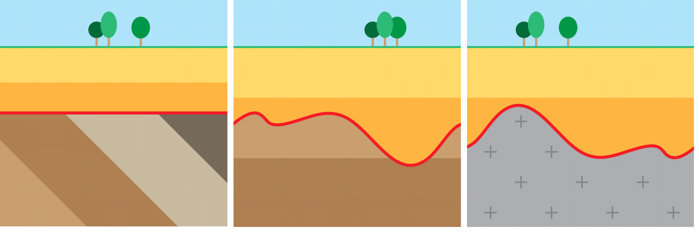
Schematic overview of the different types of unconformities. From left to right an angular unconformity, disconformity with erosion and nonconformity click to enlarge
In sequence stratigraphy, successions of strata are bounded by major depositional surfaces and unconformities which are called sequence boundaries. These sequence boundaries are an unconformity updip and a correlative conformity downdip. Where it is an unconformity, it is a surface of subaerial exposure and erosion; downdip is a correlative conformity due to more continuous sedimentation in the marine domain.
Modeling unconformities in JewelSuite Subsurface Modeling
When you model an unconformity, you actually model the erosional event which is represented by a surface between two sedimentary units. Amongst the different types of unconformities described above, the paraconformity and disconformity can be modeled as a 'normal' horizon since the layers below and above the erosional surface are parallel. In the case of an angular unconformity, by definition the layers below and above the erosional contact are nonparallel. The irregular characteristics of a nonconformity are best captured when treated as an intrusion, and will not be captured in the following paragraphs. The image below outlines the successive decisions and possible consequences when modeling an unconformity in JewelSuite Subsurface Modeling, which are described in the paragraphs hereafter.
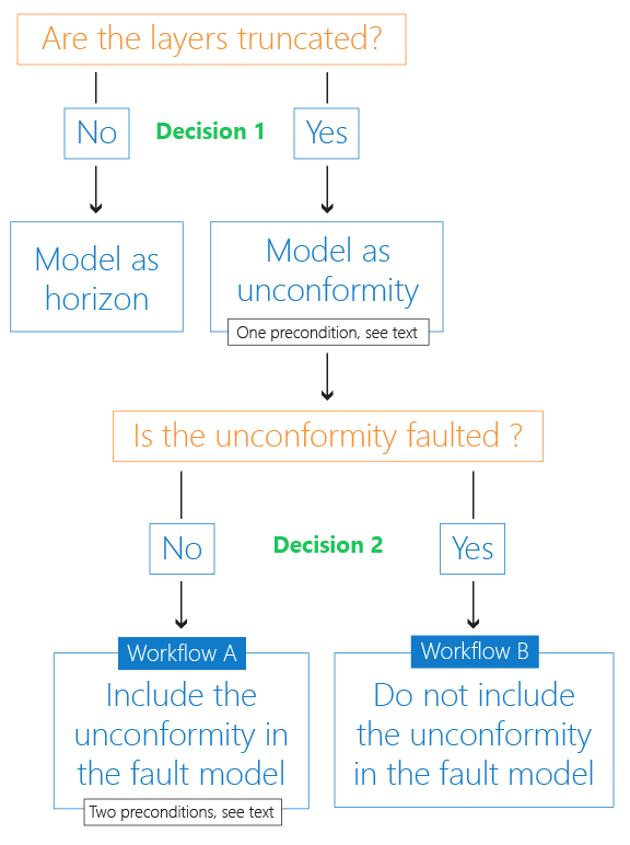
Decision tree for modeling an unconformity click to enlarge
Decision 1: Model as unconformity or horizon
When you have an unconformity in your stratigraphy, you first have to determine whether the unconformity truncates the layers below it, or not. If it doesn't, i.e. the layers below and above the unconformity are parallel, you have to set the unconformity to type 'Horizon' and model it the same way you would model a 'normal' horizon. If the unconformity truncates the layers below, i.e. when you have an angular unconformity, you have to set the unconformity to Surface type 'Unconformity' in the Inspector.
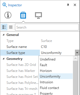
Change the Surface type into 'Unconformity' in the Inspector click to enlarge
If you have an angular unconformity in your model (and set Type to 'Unconformity' accordingly) and want to take this unconformity forward in the modeling process, there is one precondition:
- The unconformity needs to have a surface representation (tri-mesh, 2D grid or polyline set) and cannot be solely represented by a marker.
Decision 2: Faulted or not faulted unconformity
The next decision you have to make is whether the unconformity is faulted or not. This determines whether you can include the unconformity in your fault model (the preferred workflow):
- If the unconformity is not faulted, you can include the unconformity in your fault model. Faults are allowed to stick through the unconformity surface, as long as there is no offset, fault gap or cut. There are two preconditions to including an unconformity in a fault model:
- The surface representation of the unconformity is a tri-mesh.
- The surface representation needs to be field wide, i.e. it needs to cover the entire model area. The model area is defined by the boundary polygon, used during construction of the Structural Model (model > 3D Structure > Create Boundary).
- If the unconformity is faulted (i.e. the unconformity is offset by one or more faults), it cannot be included in a fault model and will 'enter' the Structural Model during the 'Construct Surfaces' step. The reason that a faulted unconformity cannot be included in a fault model is that an unconformity is both part of the discontinuities (i.e. part of the fault model) and part of the stratigraphic zonation in the 3D grid. Faulted faults are supported in the discontinuity modeling of the 3D gridding. Faulted stratigraphic surfaces are supported in the stratigraphic zonation modeling. However, the combination which is needed for faulted unconformities is currently not supported. For the modeling steps, see Workflow B further below.
For the modeling steps, see Workflow A further below.
The consequences and benefits of Decision 2 are discussed in the next paragraphs. Differences in the results of Workflow A and Workflow B are demonstrated with a modeling example, explained in the next paragraphs.
Modeling example
The modeling example (see image below) used in this chapter demonstrates the difference in modeling results between Workflow A and Workflow B. The example consists of two events 'Horizon A' and 'Horizon F', which are represented by surfaces and between which all other surfaces will be constructed. For this reason, they are placed at Level 1 of the Stratigraphic Model. Subsequently, there is an unconformity, which is represented by a surface called 'Unconformity B' and which needs to truncate the lower lying zones B-1 to B-4. The surface representations for the truncated zones are (from top to base) 'Marker C', 'Marker D' and 'Marker E'. Note that not all markers are present in all the wells. In the Stratigraphic Model, it is important that the truncated zones (Zone B-1 to B-4) are merged into one zone (Zone B) at a higher level (Level 1) because the order and way truncated zones will be built, is set by their parent zone. The zone's 'Layering Type' on the Edit Model form (model > 3D Structure > Edit Model) apply to its child zones.
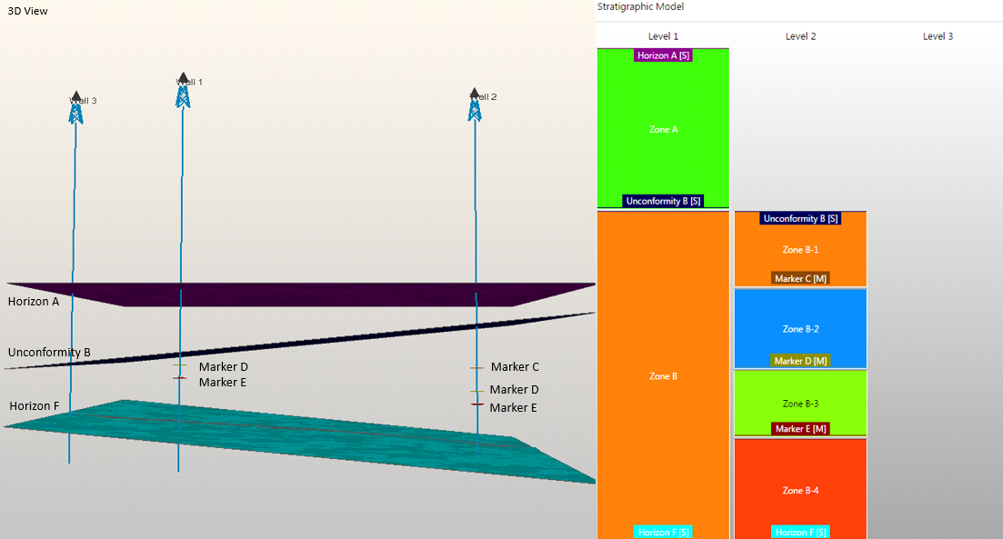
Starting point for the modeling example; at the left, a snapshot from the modeling example in the 3D View, at the right, the modeling example set-up in the Stratigraphic Model click to enlarge
Workflow A - Including the unconformity in a fault model
3D Structural Model
This paragraph describes how to model an unconformity and include it in your fault model. This is the preferred way to model an unconformity, however, Workflow A can only be applied when your unconformity is not faulted (see preconditions in previous paragraph). When you include the unconformity in your fault model, some advantages which normally only apply to faults, are also applicable to the unconformity.
Benefits:
- More accurate truncation of the surfaces due to the fact that faulted grid cells are allowed at the truncation point. When an unconformity is modeled as a horizon, truncated grid cells are not supported and the actual truncation point is determined by the closest grid cell boundary, which is generally less accurate and would lead to a pinch-out geometry.
- The surfaces of the truncated strata actually end at the truncation point and are not extended field wide (with zero thickness).
- If faults stick through the unconformity unintentionally, you can optionally 'Solve Fault Intersections' (retraction of the fault extensions towards the unconformity) resulting in a clean unconformity surface (no faults sticking through).
The following steps describe the actions and settings in order to include your unconformity in the fault model and build the 3D Structural Model. Note that only the steps where you diverge from the standard workflow are listed.
Actions and settings:
- When building your fault model, assign the unconformity to your fault model during the Assign Data step (model > Faults > Assign Data). (Note that the unconformity surface needs to be triangulated in order to be available for selection in the list on the Assign Data form.)
- When building the Structural Model, on the Assign Data form (model > 3D Structure > Assign Data) in the Fault model drop-down list, make sure you select the fault model that includes your unconformity. Upon selection, the particular unconformity will disappear from the list on the form.
- In the 3D Structure workflow process, on the Edit Model form, Zones tab, make sure the truncated zones (zone B-1 to B-4 in the modeling example) will be modeled conformable to base by setting the Layering Type of their parent zone (Zone B in the modeling example) to Conformable to base. This will ensure that the surfaces are truncated by the unconformity.
The image below shows the results of the 3D Structural Model when the unconformity is included in the fault model. From the image it becomes clear that the truncation points are optimally located and not determined by the grid cell boundaries (indicated by the vertical black lines) due to the fact that faulted grid cells are supported when an unconformity is included in the fault model.
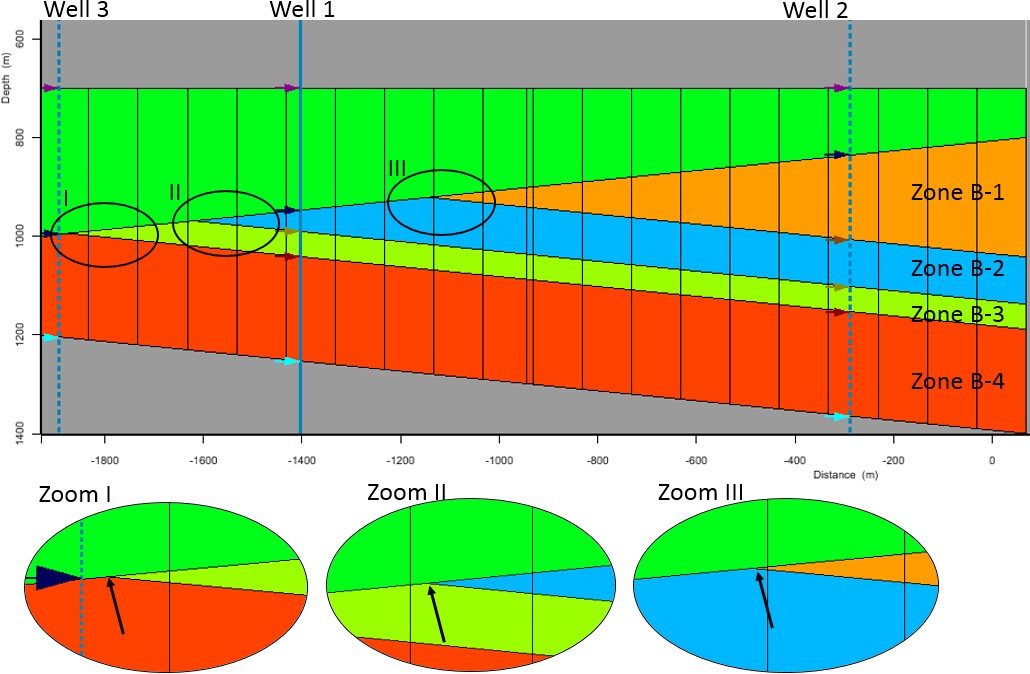
Modeling result for 3D Structural Model - Workflow A (unconformity included in fault model). The black arrows in the lower three images indicate the truncation points click to enlarge
3D Grid
This paragraph describes the steps when you move forward from your 3D Structural Model to your 3D Grid where you specify the internal K-layering of the modeled zones. It is a precondition that you have applied the actions and settings of the bullet point list described in the preceding paragraph '3D Structural Model' for Workflow A. The same benefits as described there apply to the 3D Grid, of which the most important one is the fact that the truncation points of the K-layers are accurate and not determined by the grid cell boundaries.
Actions and settings:
- In the 3D Grid workflow process, on the Edit Model form, Zones tab, you have to set the Layering Type for the zones as follows:
- Proportional: construction base to top for all the truncated zones except the uppermost truncated zone (in the modeling example, these are zones B-2 to B-4). This ensures that the internal K-layers laterally exist everywhere where the zone exists, and that the uppermost K-layers of the zones are not 'cut away' at locations where zones are thinner.
- Conformable to base for the uppermost truncated zone (in the modeling example, this is zone B-1). This ensures that the internal K-layers of the uppermost zone are truncated by the unconformity above.
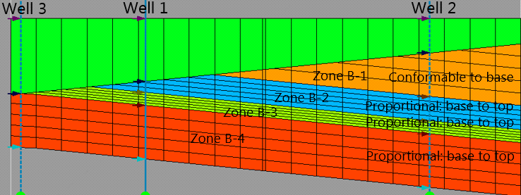
Modeling result for 3D Grid - Workflow A (unconformity included in fault model). Each zone contains five K-layers, which are optimally truncated by the unconformity because the truncation points are not determined by the grid cell boundaries (vertical black lines) click to enlarge
Workflow B - Not including the unconformity in the fault model
3D Structural Model
This paragraph describes how to model an unconformity without including it in a fault model, which is imperative when the unconformity is faulted. The unconformity will 'enter' the 3D Structural Model the same way as a 'normal' surface, i.e. during the assign data step in the 3D Structure workflow process. There are some benefits and disadvantages to this method:
Benefits:
- The unconformity can be faulted.
- Less manual editing in the fault model.
Disadvantages:
- At the truncation point, the horizons of the truncated strata do not 'end' but continue to exist area wide with a zero thickness zone between the unconformity and the below horizon.
- Less accurate truncation of the horizons. The actual truncation point is determined by grid cell boundaries, see image below. Note that the grid cell size is determined by the resolution of the modeling parameters.
The following steps describe the actions and settings to model an unconformity without including it in the fault model. Note that only the steps where you diverge from the standard workflow are listed:
- When building the Structural Model, on the Assign Data form (model > 3D Structure > Assign Data) select the unconformity by checking the box together with the other horizons.
- In the 3D Structure workflow process, on the Edit Model form, Zones tab, you have to set the Layering Type of the parent zone (Zone B in the modeling example) of the zones that need to be truncated (zone B-1 to B-4 in the modeling example) to Conformable to base. This will ensure that the surfaces are truncated by the unconformity.
The image below shows the results of the 3D Structural Model when the unconformity is not included in the fault model. From the image it becomes clear that the truncation points are located at the grid cell boundaries (indicated by the vertical black lines) showing a pinch-out geometry rather than a clean truncation.
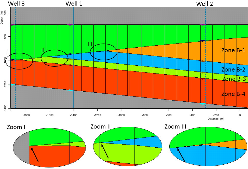
Modeling result for 3D Structural Model - Workflow B (unconformity not included in fault model). The black arrows in the lower three images indicate the truncation points, which are located at grid cell boundaries, indicated by the vertical black lines click to enlarge
3D Grid
This paragraph describes the steps when you move forward from your 3D Structural Model to your 3D Grid where you specify the internal K-layering of the modeled zones. It is a precondition that you have applied the actions and settings of the bullet point list of the preceding paragraph '3D Structural Model' for Workflow B. The same benefits and disadvantages apply as described there, of which the most important one is the fact that the truncation points of the K-layers are determined by the grid cell boundaries (see image below).
Actions and settings:
- In the 3D Grid workflow on the Edit Model form, Zones tab, you have to set the Layering Type of all zones stratigraphically below the unconformity to Conformable to base. This ensures that the internal K-layers are truncated by the unconformity. An important disadvantage is that at those locations where zones are thinner, the uppermost K-layers of these zones might be 'cut away' due to the fact that K-layers have a constant thickness when using 'Conformable to base'.
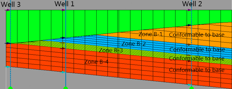
Modeling result for 3D Grid - Workflow B (unconformity not included in fault model). Each zone contains five K-layers, truncated at the grid cell boundaries (indicated with the vertical black lines) click to enlarge
Modeling local erosive surfaces
Complex local erosive events or truncations such as valleys with cuts and infills, cannot be modeled via the workflows described above. The architecture of channel systems (ranging from channel stacks and amalgamated channels to isolated bodies) requires multiple unconformities at several (deeper) hierarchy levels, severely complicating the hierarchy of the Stratigraphic Model. Also, in JewelSuite Subsurface Modeling an unconformity needs to be field wide, while incised-valleys and channels typically are local phenomena.
Schematic of a local unconformity formed by a channel click to enlarge
Only if your channel fill architecture is relatively straightforward and you can make the unconformity field wide, you can use the workflows as described in the previous paragraphs. If your architecture is more complex, you can use MPS to create (local) channels in a facies model.